If you can understand how a wiring diagram for a dual run capacitor works, then you can be better equipped to diagnose and fix. Web this post is about the capacitor start capacitor run compressor ptc relay wiring diagram.
1ph Run Capacitor Wiring Diagram
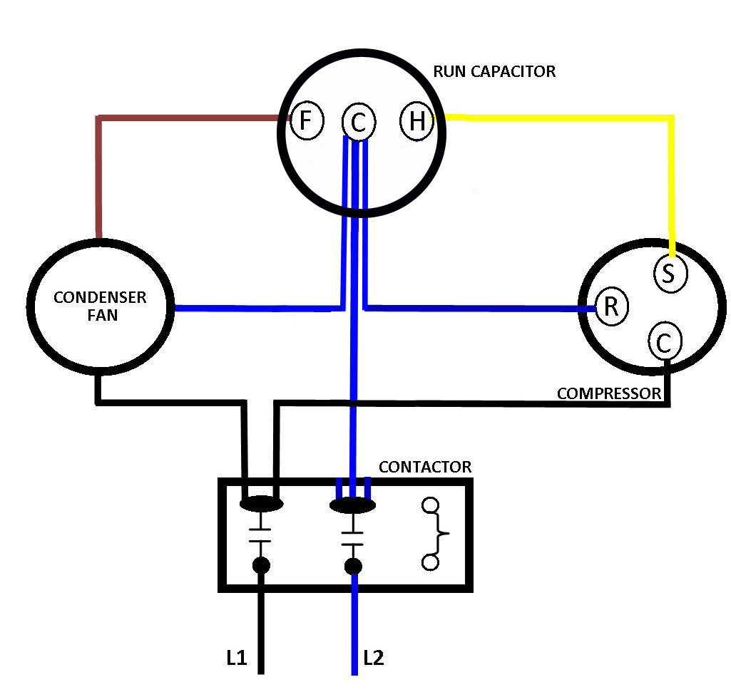
Running Capacitor Wiring Diagram. This will show you which wires need to be connected to which terminals on the capacitor. When it comes to motors, there is nothing more important than understanding the wiring diagram for capacitor start run motor. Web a dual run capacitor is made up of two capacitors that are connected in parallel, and it is used in many ac systems to help manage power and ensure the right amount of power is sent to each component.
Web There Are Typically Three Capacitors In A Ceiling Fan Motor—The Run Capacitor, The Start Capacitor, And The Auxiliary Capacitor.
A complete connection has shown how to connect the starting and running capacitor to a compressor ptc (positive temperature coefficient) relay. Web by wire draw | october 10, 2022. Web this article will provide an overview of how to create a wiring diagram for a start run capacitor, as well as the different types of diagrams available.
Web A Titan Pro Run Capacitor Wiring Diagram Is A Visual Representation Of The Electrical Connections And Components Of Your System.
Your pump may be provided with a single run capacitor, and no start capacitor or potential relay. Web a dual run capacitor is made up of two capacitors that are connected in parallel, and it is used in many ac systems to help manage power and ensure the right amount of power is sent to each component. Next, locate the electrical schematic for your motor.
Web A Wiring Diagram For An Ac Unit Capacitor Is An Essential Tool When Dealing With Any Electrical Project.
If you can understand how a wiring diagram for a dual run capacitor works, then you can be better equipped to diagnose and fix. Procedure wire z2 is the connection to the start winding. The diagram will usually include the common connection points for the compressor and other components that are associated with the operation of the compressor.
This Diagram Provides A Clear And Concise Visual Representation Of The Electrical System That Is To Be Used In The Project.
Web wiring diagrams seem to suggest that voltage energizes the hot leg of the circuit and current flows through the run windings and then returns via the neutral leg. Web a wiring diagram for compressor use running capacitor is used to determine the proper wiring for the compressor. Wire u1 is the common connection for both windings.
Switching The Link Positions Reverses The Winding Phases Relative To Each Other Reversing The Direction Of Rotation.
For more information, refer to the wiring diagram further on in this article. Web first, locate the motor's motor control wiring diagram and ensure that all connections are correct. This type of motor is used in many industrial applications and is designed to provide a powerful, yet efficient and reliable power source.
Web Cscr Capacitor Start Capacitor Runwiring Diagram.hi Frends Hum Ne Diagram Ke Zareye Aap Ko Ac Me Cscr Ki Wiring Kaise Karte Hai Btaya Hai.agar Aap Logon Ko.
Web capacitors are widely used in automotive electronics and now even more so with the advent of hybrid vehicles. This will include information about the motor's voltage, current, and capacitance values. Web 3 in 1 start capacitor basically has 5 wires, 2 wires to power it, and the other 3 wires connected to the pins on the side of your compressor.
Web Here We Will Illustrate The Proper Wiring For A Motor To A Run Capacitor.
Web wiring diagram for dual run capacitor: It is designed to show all of the components, their respective locations, and how they are connected. How to wire a run capacitor to a motor blower & condenser hvac wiring the above illustration does not cover every single type of motor wiring available on the market.
Web Start Capacitors Are Wired Into The Auxiliary Winding Circuit Of The Motor And Are Disconnected From The Main Winding Circuit By The Centrifugal Switch Once The Motor Has Reached A Predetermined Speed (Usually 75% Of The Rated Speed).
The only thing missing from this graphic is the motor rotation wiring which is a yellow and a purple wire that will reverse the direction of the motor depending on what direction is needed. Web run capacitor at the top, start capacitor at the bottom. This gives the following circuit diagram.
This Will Show You Which Wires Need To Be Connected To Which Terminals On The Capacitor.
Unlocking the potential of your circuitwhen it comes to electrical projects, the wiring diagram is your map. You need it to know where everything goes and how to power it up. Web this post is about the capacitor start capacitor run compressor ptc relay wiring diagram.
It Shows The Pathways Of Electricity From The Power Source To The Device.
Main winding (running winding) and 2nd is auxiliary. With this information in hand, you can then wire the dual run capacitor according to the schematic. Wire u2 is the connection to the run winding.
But What Happens When You Need To Wire Something That Requires A Dual Run Capacitor?
In the ptc relay wiring diagram. At first, notice the three wires coming out of one side and two black wires coming out of the other side at the top of the capacitor. Then, it’s time to look at the wiring diagram.
Web Single Run Capacitor Wiring Diagram The Graphic Is A Reproduction Of A Fasco Motor.
Problem there i guess is that both windings would be in phase and thus no spin created for the rotor. It also shows any other components that may be needed to complete the circuit. When it comes to motors, there is nothing more important than understanding the wiring diagram for capacitor start run motor.
This Document Will Help You To Wire The External Capacitor To The Pump.
The pins on the compressor are placed shaping a triangle. This videos is part of our automotive electronic technology and wiring diagram series. Without a capacitor, the same thing would happen to the start windings.
Ac Outdoor Unit Capacitor Wiring Diagram Ac Capacitor Cost And

Series Capacitor Wiring Complete Wiring Schemas

Dayton Capacitor Start Motor Wiring Diagram Free Wiring Diagram

1ph Run Capacitor Wiring Diagram

Running Capacitor 6uf 440V MagicAire Industries Inc.

Motor Run Capacitor Wiring Diagram What Is The Wiring Of A Single

Types of Single Phase Induction Motors Single Phase Induction Motor

How To Replace Start Capacitor On Air Compressor Sante Blog
