Web let’s look at a waveform diagram to see how this works. Here are few applications where.
How to use Rotary Encoder with Arduino
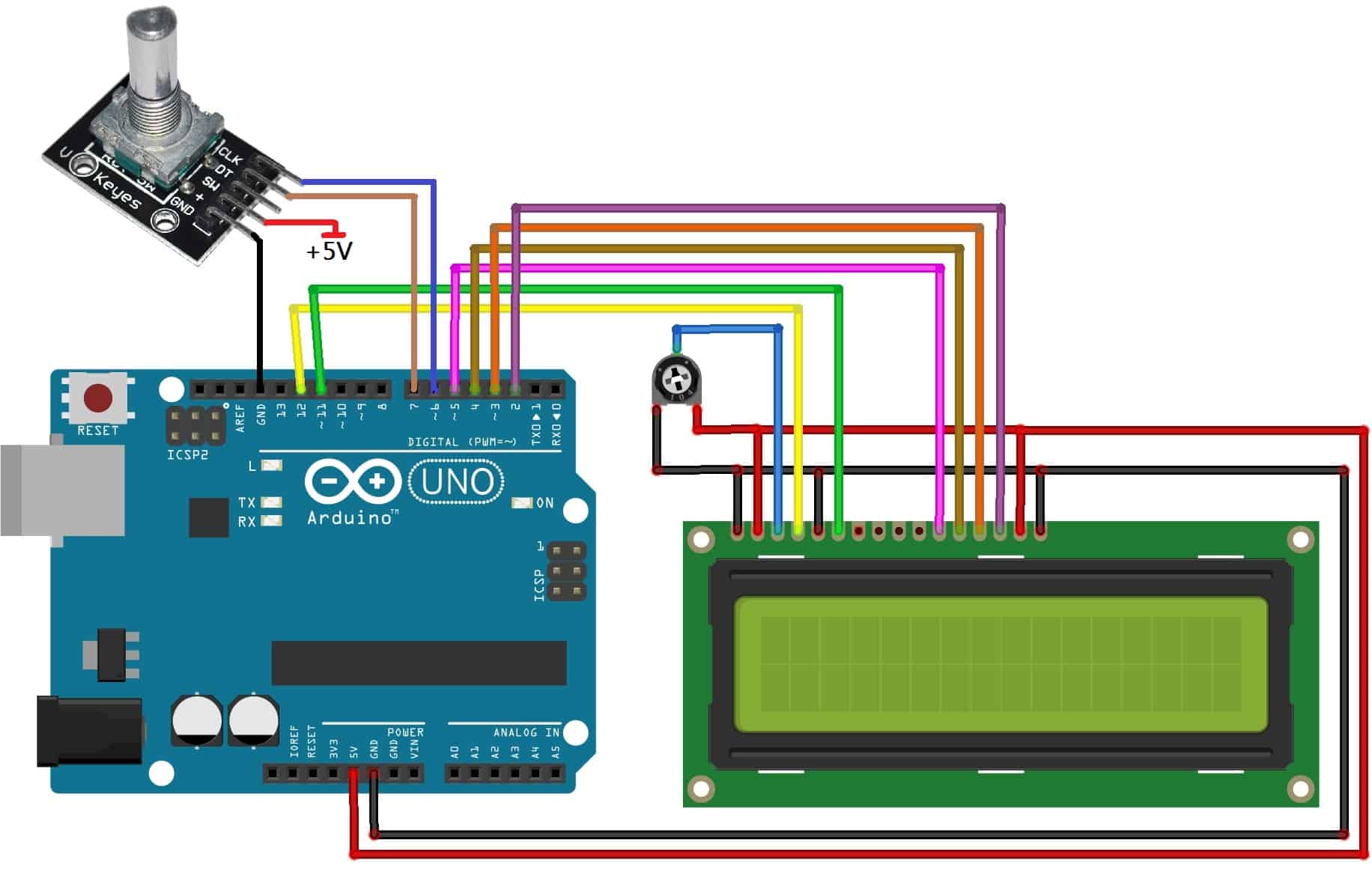
Rotary Encoder Circuit Diagram. Also, check the full working video given at the end. The commonly used rotary encoder is an incremental. There is a select switch associated with the rotary encoders that can be activated by pushing the knob.
Web Arduino Uno Lcd Display Introduction To Rotary Encoders A Rotary Encoder Is An Input Device That Provides The Information About The Direction And Amount Of Rotation Of The Knob.
Encoders and decoders worksheet comments The circuit is built around arduino uno. The first two pins are ground and vcc which is.
Web Find Every Electronics Circuit Diagram Here, Categorized Electronic Circuits And Electronic Projects With Well Explained Operation And How To Make It Procedure And Then New Circuits Every Day, Enjoy And Discover Electronics.
Rotary encoders are classified into two types: Web rotary encoder debounce circuit the elm401 is an 8 pin integrated circuit that is used to ‘debounce’ the signals from a mechanical rotary (quadrature) encoder. The resulting ladder diagram and the corresponding ladder diagram:
The Rotary Encoders Each Have Two Digital Outputs In A Quadrature Format That Can Be Read By The Upstream Microcontroller.
So just draw something that says what it is. The module is made with very generic and readily available components, and all you need is three resistors and the encoder itself to build it yourself. However, in this circuit we will only use 3 of the pins.
Web Pic16F877A Rotary Encoder Interfacing Circuit Diagram.
Can work on low voltages; When you turn the knob clockwise the dt pin goes high first. Below is the pinout diagram.
And Also Learn About Rotary Encoder And How It Works With Example Arduino Program Codes.
Web a rotary encoder (rt) is a device that you can rotate infinitely. A hall effect sensor has the ability to vary its output voltage depending on the magnetic field that is. The resulting circuit diagram the circuit is:
Web The Following Wiring Diagram Shows Wiring Up The Rotary Encoder To The Itsybitsy To Match The Code Example.
A and b are the signal pins. Web a rotary encoder is a type of position sensor that converts the angular position (rotation) of a knob into an output signal that can be used to determine which direction the knob is turned. Web general information the board features two rotary encoders, a standard digital switch and an output led.
20 Steps Or Cycles Per Revolution;
Web circuit diagram for rotary encoder module. Web let’s look at a waveform diagram to see how this works. This includes circuit boards, relays, switches, wires, and other components.
C Is The Common Ground For A And B.
The circuit diagram of the application is given below. Web rotary encoder module features and specifications. A nokia 5110 lcd is used for graphical interface.
The 3 Pins We Will Use Are The 3 Pins In Front.
Basically this step is the minimum amount you can rotate the encoder to register any change. Web a rotary encoder wiring diagram is a document that shows the location, type and size of all the components required to connect your rotary encoder correctly. How rotary encoders work a rotary encoder makes use of two core components:
Web Equation Collection Summary The Collection Of Equations Is Summarized Here:
Web a circle with terminals, maybe with a rotational arrow in it. Web we will use the encoder for navigation, data entry and selection. It’s used to create a graphical representation of a system’s functioning, allowing users to better understand how the various components interact.
A Box With The Words Rotary Encoder Written In It.
Where m274 rotary encoder modules are used? A magnetic rotor, and hall effect sensors. Leave a reply cancel reply.
Here Are Few Applications Where.
Web this guide uses a mechanical, incremental rotary encoder. This encoder generates an electrical signal based on the rotating movement like either analog or digital. At the same time the clk pin is low:
These Pins Are Pin A, Pin B, And Ground.
On most rotary encoders, when you rotate them you will feel a bump (known as steps), and most rts have about 12 of these per rotation (some have 24 or more). Web in this detailed tutorial learn how to interface a rotary encoder with arduino and display the encoded directional values on 16x2 lcd display when rotated in clockwise and anti clockwise directions. There is a select switch associated with the rotary encoders that can be activated by pushing the knob.
A Box With Multiple Switches In It.
A rotary encoder isn't really that pictorial a device, hence most things say what it is either within it or next to it. Web there are many different types of rotary encoders which are classified by either output signal or sensing technology. Below is the picture of final setup after connecting the components according to circuit diagram:
The Particular Rotary Encoder That We Will Use In This Tutorial Is An Incremental Rotary Encoder And It’s The Simplest Position Sensor To Measure Rotation.
Web a rotary encoder circuit diagram is a fundamental tool for anyone interested in learning more about electronic components and circuits. We have used a single 1k resistor for the contrast of the lcd instead of using a potentiometer. Below is the graph of the pulses given out from the rotary encoder pin a and pin b.
The Low Power Cmos Technology Used Ensures That Only A Very Small Current Is Required Over The Entire 2.0 To 5.5 Volt Operating Range.
When you rotate the knob, a and b come into contact with the common ground pin, in a particular order depending on the direction you are rotating the knob. Also, check the full working video given at the end. Web the complete circuit diagram for interfacing rotary encoder with arduino is shown in the picture below the rotary encoder has 5 pins in the order shown in the label above.
The Commonly Used Rotary Encoder Is An Incremental.
When the encoder is rotating a square wave is output from both the dt pin and the clk pin.
How to use Rotary Encoder with Arduino

DC Motor control with rotary encoder and PIC MCU mikroC Projects

LED Chaser using Arduino and Rotary Encoder Circuit Diagram & Code

Embedded Engineering Rotary Encoder Interfacing with PIC Mirocontroller

Interfacing Rotary Encoder with AVR Microcontroller (ATmega8)

How to Use a Rotary Encoder in an MCUBased Project LEKULE BLOG

How Rotary Encoders Work Electronics Basics The Geek Pub

DC Motor speed/direction control using PIC16F877A and rotary encoder
