Describe how the current varies in a resistor, a capacitor, and an inductor while in series with an ac power source. We know that the current is the same in series whereas the supply voltage (ac) gets divided among the passive elements.
figure 11 parallel rlc circuit Electrical Academia
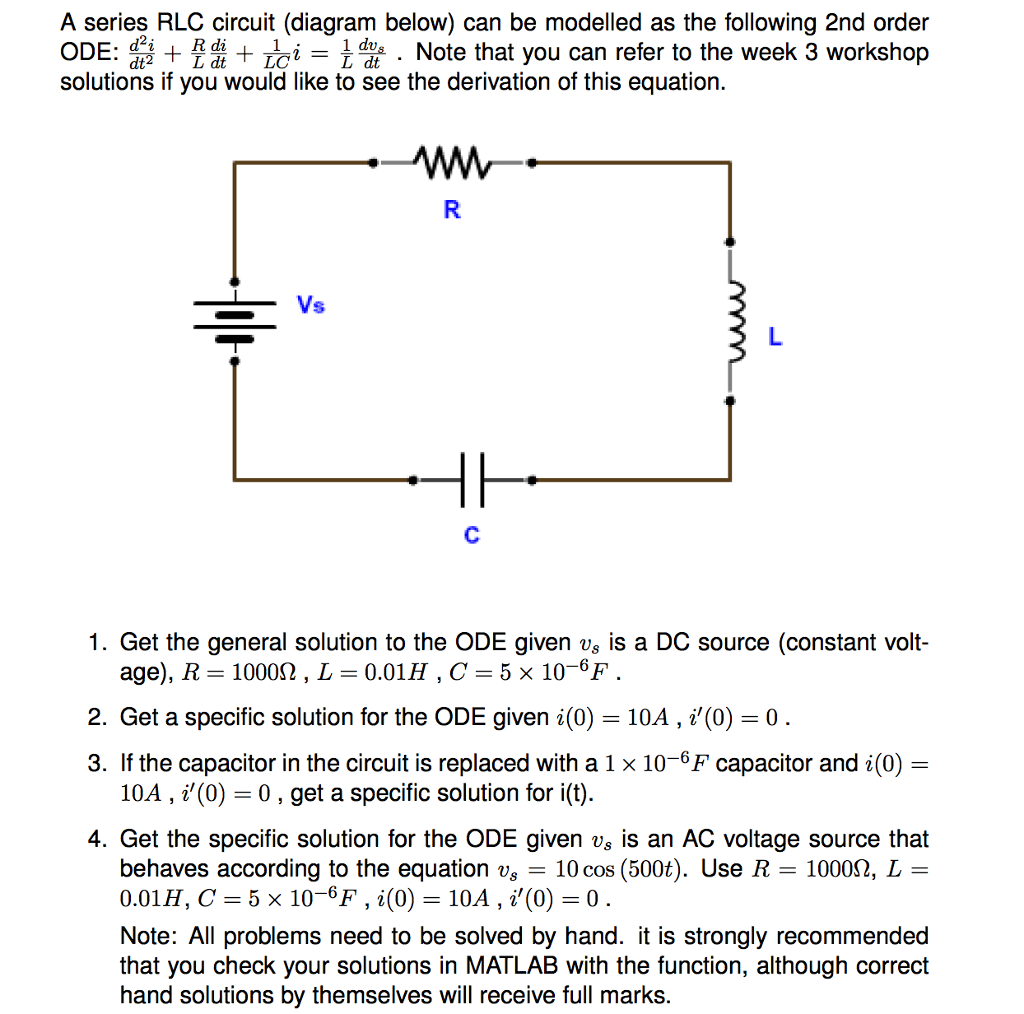
Rlc Series Circuit Diagram. The image below shows a circuit diagram of an rlc circuit and its associated electrical behavior. The circuit consists of a resistor with resistance , an inductor with inductance , and a capacitor with capacitance. This is the last circuit we'll analyze with the full.
The Image Below Shows A Circuit Diagram Of An Rlc Circuit And Its Associated Electrical Behavior.
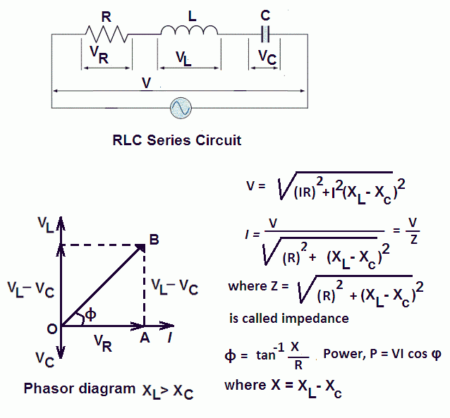
Web the phasor diagram for a series rlc circuit is produced by combining together the three individual phasors above and adding these voltages vectorially. So draw the voltage phasor, v r along same. For drawing the phasor diagram for rlc series circuit, the current is taken as reference because, in series circuit the current in each element remains the same and the corresponding voltage vectors for each component are drawn in reference to common.
Web Interpret Phasor Diagrams And Time Domain Plots For Component Voltages And/Or Currents In Seriesparallel Rlc Circuits.
The value of the phase difference depends on the values of r, c, and l. Fiore via source content that was edited to the style and. (b) a comparison of the generator output voltage and the current.
When Alone In An Ac Circuit, Inductors, Capacitors, And Resistors All Impede Current.
The current in an rlc series circuit is determined by the differential equation. Series rlc circuit and equations. How do they behave when all three occur together?
What Is Rlc Series Circuit?
Web parallel rlc networks can be analysed using vector diagrams just the same as with series rlc circuits. Web the rlc circuit is depicted in the diagram below: For the purpose of understanding let us consider a simple circuit consisting of a capacitor and resistor in series with a power supply (5v).
The Voltage Across The Capacitor C That Is V C Is Drawn Lagging The Current I By A.
Before we start with each topic let us understand how a resistor, capacitor and an inductor behave in an electronic circuit. Web figure 15.12 the phasor diagram for the rlc series circuit of figure 15.11. The inductive reactance value of an inductor increases linearly as the frequency across it increases.
Web Draw The Circuit Diagram For An Rlc Series Circuit.
At any instant, the voltage across the rlc combination is v r ( t ) + v l ( t ) + v c ( t ) = v ( t ) , v r ( t ) + v l ( t ) + v c ( t ) = v ( t ) , the emf of the source. A series rlc circuit is the series combination of resistance, inductance and capacitance. In case of series rlc circuit;
In Case Of Resistor, Both Voltage And Current Are In Same Phase.
Describe how the current varies in a resistor, a capacitor, and an inductor while in series with an ac power source. We know that the current is the same in series whereas the supply voltage (ac) gets divided among the passive elements. Since the elements are in series, the same current flows through each element at all points in time.
Web The Graph Of Inductive Reactance Against Frequency Is A Straight Line Linear Curve.
Web series rlc circuits. If we observe the impedance diagrams of series rl and series rc circuits as shown in fig. Rlc series circuits with ac.
The Name Of The Circuit Is Derived From The Letters That Are Used To Denote The Constituent Components Of This Circuit, Where The Sequence Of The Components May Vary From Rlc.
Phasor diagram & phase angle in this article, we will discuss the rlc series ac circuit and will analyze its behavior in the application of sinusoidally varying ac voltage. Explain the significance of the resonant frequency. The total impedance (z) is equal to the vector sum of the circuit’s reactance and resistance.
It Is Also Called The Rlc Circuit In Series.
Impedance when alone in an ac circuit, inductors, capacitors, and resistors all impede current. Draw the circuit diagram for an rlc series circuit. Web basic principle of rc/rl and rlc circuits:
Web Series Rlc Circuit Impedance Diagram.
Web calculate the impedance, phase angle, resonant frequency, power, power factor, voltage, and/or current in a rlc series circuit. Illustration of the series rlc circuit. So, let’s start with the basic introduction of the rlc series circuit.
Interestingly, Their Individual Resistances In Ohms Do Not Simply Add.
Find out more about eectrical device & equipment in linquip click here what is rlc circuit? Web this demonstration shows a phasor diagram in an ac series rlc circuit. Web (figure 12.3.1) figure 12.3.1 (a) an rlc series circuit.
Circuitglobe.com) Series Rlc Circuit Analysis A Resistance, A Capacitance, And An Inductance Are Connected In Series Across An Alternating Supply In A Series Rlc Circuit.
Explain the significance of the resonant frequency. Use phasors to understand the phase angle of a resistor, capacitor, and inductor ac circuit and to understand what that phase angle means. Resistor, capacitor and inductor are connected in series;
The Circuit Consists Of A Resistor With Resistance , An Inductor With Inductance , And A Capacitor With Capacitance.
Web a formal derivation of the natural response of the rlc circuit. This is the last circuit we'll analyze with the full. Its impedance (z r) remains the same in dc and ac regime and is equal to r (in ω).
Web An Rlc Circuit Is An Electrical Circuit Consisting Of A Resistor (R), An Inductor (L), And A Capacitor (C), Connected In Series Or In Parallel.
Web phasor diagram & phase angle what is rlc series circuit? The impedance diagram for a typical series rlc circuit, inductive in nature, is shown in figure 5 and can be summarized as follows: However, the analysis of parallel rlc circuits is a little more mathematically difficult than for series rlc circuits when it.
Web The Figure Below Shows The Phasor Diagram Of The Series Rlc Circuit.
Therefore, inductive reactance is positive and is directly proportional to frequency (. Web this circuit diagram is shown in the figure below.

figure 11 parallel rlc circuit Electrical Academia
Solved A series RLC circuit (diagram below) can be modelled

RLC Series Circuit electrical and electronics technology degree
RC RLC RL Series Circuits your electrical guide

RLC circuit Wikiversity

RC RLC RL Series Circuits your electrical guide

Passive Components in AC Circuits with Equations Electrical Academia

Series RLC Circuit Analysis & Example Problems Electrical A2Z
